Sorry for the delay continuing this series. Actually, part of the delay had to do with developing an hands-on for explaining how gears work on a bicycle together with a colleague, using an arduino…
So, the basis of the logger is an arduino, which we presented lately as the “thing that can do things“. There are several arduino platforms depending on what you want to do. For our project we chose an arduino uno:
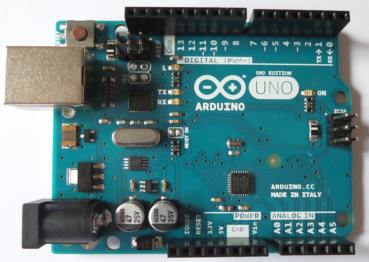 Photo by Clic17 via Wikipedia, CC-BY-SA 4.0
Now, an arduino uno can do much more than just reading sensor data like we want to do, but it’s rather easy to make projects real without having to solder anything, it comes with a quite easy to understand coding language and there is a broad international community experimenting with it, so you probably find answers to your questions at the official arduino forum https://forum.arduino.cc/ or somewhere else on the web.
To work with an arduino you will connect the sensor and other devices you need to the ports of the arduino. You got digital ports (0 to 13), analog ports (A0 to A5) and some ports for connecting to power (marked 3.3 V, 5 V and GND). We take a close look on what we connect how later on.
First, we need another useful device, a data logger shield. So, what is a shield you ask? Well, as your arduino comes out of the box, it is a generalist. It can do anything, from showing the bike speed to logging your climate data. You connect it to all the parts you need for your specific project. Depending on the project, this can be a lot of wires, resistors, capacitors, switches… So, for some specific tasks you need for certain projects some fine people have developed boards that have everything you need on them and which you can connect to the arduino by simply “clicking” it on. So, the shield sits on the arduino like a backpack, is ready to perform certain tasks and you still have a reasonable amount of ports for your specific task, although some ports are now used for the connection.
And what is a data logger shield? Well, look here:
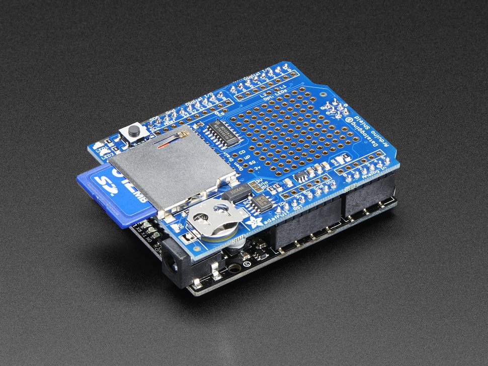
Taken from Adafruit website https://www.adafruit.com/product/1141
A data logger shield has two very useful devices: a SD card reader to log your data for further use and a real time clock (RTC). We need a real time clock because an arduino is incredibly dumb. When we tell it what time it is, it just remembers it as long as it got power. When we disconnect it from the power source it immediately assumes that it’s 0 o’ clock. The RTC has a small battery on board that safeguards the arduino remembers the time even when disconnected.
When we clicked the data logger shield to the arduino we can start wiring our logger. We can do that by soldering the wires directly to the shield, which comes with a convenient hole matrix for this task, or we can use a little breadboard and breadboard cables to do the wiring like in our example. For long-term use, I’d prefer soldering because it is less vulnerable to bad contacts. You can see the exact wiring in this scheme:
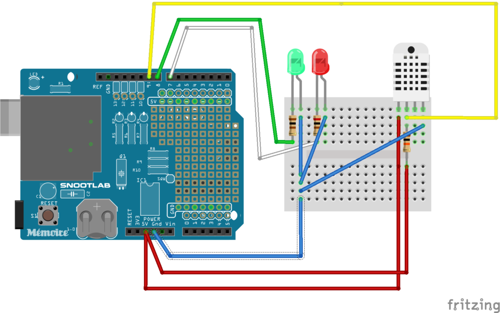
The data pin of the sensor is connected to digital port 9, the green LED over a 100 Ohm resistor to digital port 8, the red LED over a 200 Ohm resistor to digital port 7. The “buckled (short) legs” of the LEDs, which are the minus pole, and the ground pin of the DHT22 are connected to the GND port. The power pin of the DHT22 and the data pin over a 10 K Ohm resistor are connected to the 5 V power port.
For our logger, we mounted the breadboard with the sensor and the two LEDs on the outside of the casing, while arduino and shield are inside of the casing. You can see the breadboard wires being connected from the inside to the outside:
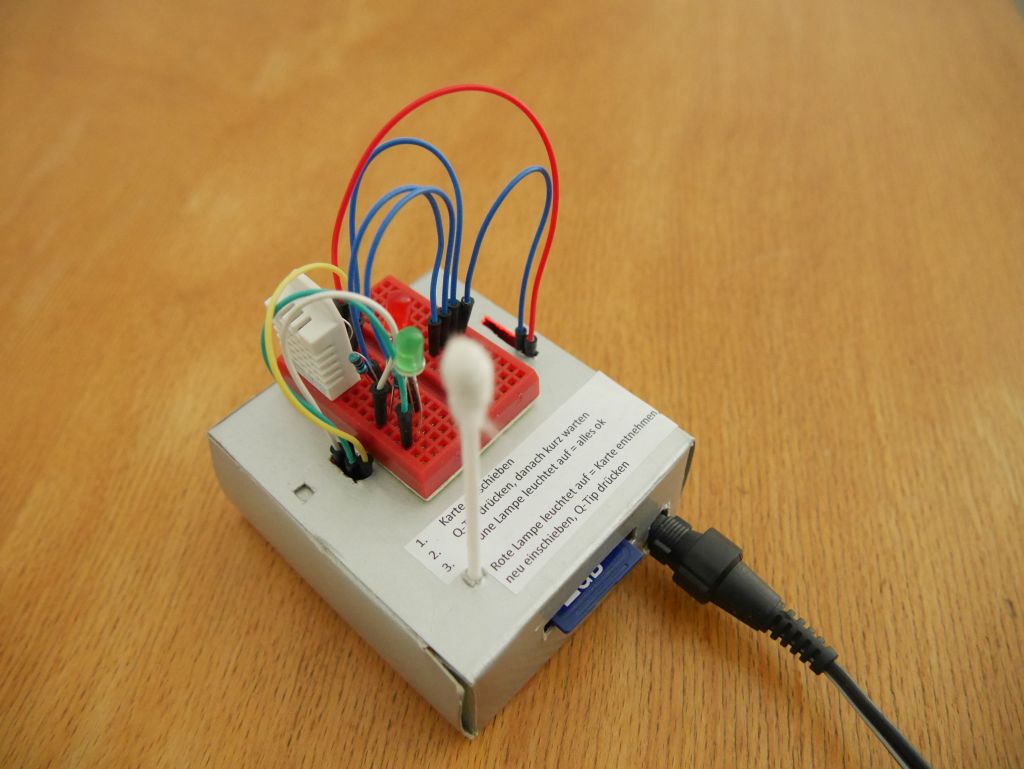
Finally, we need something that allows us to push the reset button in case we want to restart the arduino. In our case we used a q-tip with a broad plastic peg on one end.
Next up, we will take a look at the coding for our logger.
Angela Kipp
Read the other posts for this project:
- Build Your Own Data Logger – Investigating Your Climate Graphs
- Build Your Own Data Logger – We Want Fahrenheit!
- Build Your Own Data Logger – Processing Data With Microsoft Excel
- Build Your Own Data Logger – Processing Data with OpenOffice Calc
- Build Your Own Data Logger – The Software, Telling the Logger to Log
- Build Your Own Data Logger – Arduino, the Datalogger-Shield and the Wiring
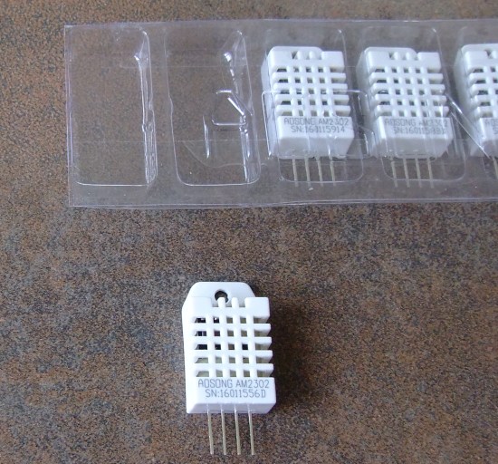
- Build Your Own Data Logger – The Sensor, Heart of the Logger
- Build Your Own Data Logger – Quick Start Guide
This post is also available in Russian translated by Helena Tomashevskaya.